Digital Callipers
| Digital Callipers |
|---|
| [[Image:{{#arraymap:Digital-callipers.jpg}}|200px]] |
| What: |
| Replace the board in the digital callipers with one that won't drain the battery. |
| Participants: |
| {{#arraymap:User:Bracken, User:Daverowntree|,|x|Has participant::x}} |
Problem
Those cheap digital calipers we all buy use 22μA when on and 18μA when off, thus will drain your 1.5V LR44 battery if you leave them off.
Potential Solutions
Take the Battery Out
Pros
- Reduces consumption to 0μA.
Cons
- Ugh!
Install a Switch
Pros
- Reduces consumption to 0μA.
- Easy to use.
- Easy to implement.
Cons
- Easy to implement.
- Prohibitively so.
Replace the electronics.
Pros
- Now we're talking.
- Get "off" consumption under 1μA.
- Features!!
Cons
- None whatsoever, I can't think of any.
The existing circuit
It's interesting, it seems the sensor is made entirely on the PCB, which impressive.
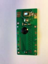

The circuit appears to be as so.
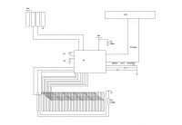
- The LCD is connected by 19 lines, this is boring and we can work it out later. Just wire it up to some IO.
- C1 seems to be a de-coupling cap.
- I don't know what C3 is, but there is no signal across it, just a low (10s of mV) DC charge.
- C2 is another low charge, with a periodic dip corresponding to possibly serial transmissions.

- There are three buttons, the pad for the 4th appears to be NC and there is no hole in the case.
- There is an array of 48 strips arranged into 6 groups of 8 connected to one IO line each.
- There is another strip wired quite strangely, it is connected with a possibly guard trace originating from IO, then the other end runs seperated by a ground plane to the other end of the device and is terminated to ground with a 210K resistor (R1).
- There is another plane on the back whose via is under the black blob.
- There serial port would be interesting as I'm not sure what the protocol is, but we will do our own so it's actually boring, but here is anyway:


Reverse Engineering
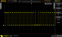
Measuring across R1 with a short ground loop is quite messy:
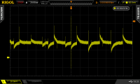
The pad end of this trace is cleaner, given the voltage level and waveform I think this is an antennae.

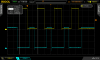
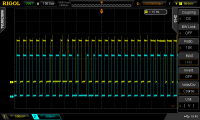
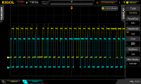
The array of pads are clearly being driven by the uC, I think these serve as something like field coils, here's the first group, which makes pads 1, 9, 17, 25, 33 & 41:
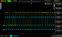
Here's group 1 (yellow) plotted against group 2, 3, 4, 5, 6 & 8 (blue)(sorry, I lost 7).


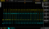
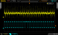
Here's group 1 against the antennae.
Here's group 1 against the antennae with the device on its encoder and the scope limited to 20MHz.
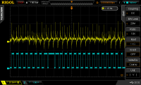
So I think we're dealing with some sort of capacitive coupling, There's certainly a periodic nature to the ringing on the antennae, but I'm also certain only my scope can see that ringing, not the uC.
Further investigation is needed, we should:
- Attempt to trace that last pad on the reverse.
- See if we can detect a change by moving the device over the encoder. Possibly set the scope to pulse trigger on the long pulse seen at pad group 1, then repeat the last measurement and slide the sensor up and down the encoder. We'll need some good fly-wires adding.
- Measure the pitch of the sensor.
- Google says the plate I didn't measure is the actual receiver, it should have peaks making a sin wave whose phase to something relates to the position of the reader. The encoder is an arrangement of conductors. We really need to get some wires attached and measure this properly assembled. We can also make our own encoder!!! Possibly helpful to: Project:DRO the lathe.